
To address the growing demand for electricity in Mumbai, the Reliance Infrastructure has set-up new Extra High Voltage (EHV) substations. This is expected to help in bolstering the cities transmission grid
As India’s economic growth accelerates, the power generation and distribution sector will play a critical role in realising this growth. According to a recent McKinsey report, India’s demand for power is expected to cross 335 GW by 2017. Assuming an average GDP rate of 8 per cent for next 10 years, the report estimates India will require a generation capacity of 415-440 GW, after adjusting for a modest 5 per cent spinning reserve.
While reform measures are being implemented to control the distribution side, power generation remains the single most critical area of concern for the country. This is because capacity additions to bolster power generation are not commensurate with the estimated peak demand for power.
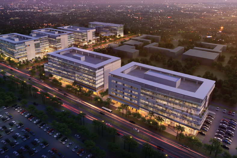
Electrical infrastructure is a critical component of the country’s overall infrastructure. With rapid urbanisation, the need for a robust electrical infrastructure in urban areas, mainly the metros, has come to the fore. For instance, Mumbai, the country’s business capital, is witnessing major restructuring to meet growing commercial demand. A burgeoning population, booming industrial projects and the influx of global business entities setting up operation in the city has further increased the demand for electricity.
The existing government-run power utility providers are unable to meet this demand. Inadequate power generation capacity has underpinned the importance of capacity building in the power sector. To address this demand-supply gap, Reliance Infrastructure, the country’s largest private utility provider, picked up the gauntlet to re-engineer the power generation and distribution sector in Mumbai.
Reliance Infrastructure has always been at the forefront of innovation in its operations. The company has always used latest tools and technologies for maintaining the high network availability. To implement capacity addition in the power generation process, Reliance Infrastructure has introduced state-of-the-art generation compact EHV substations in Mumbai.
What are EHV substations? Electric power transmission is the process in the transfer of electrical power to consumers and refers to the bulk transfer of electrical power from one location to another. Transmission plays a very important role in bringing power from distant generator locations to the load centres. The EHV substations form the heart of the transmission infrastructure and occupy a position of utmost importance in meeting the overall power requirements.
EHV stations, which are generally AIS (Air Insulated Sub-Station), are located outside the cities and sub-transmission levels are fed to the load centers. With increase in population density and changing lifestyles, locating EHV networks near load centers has become imperative. Moreover, with most Indian cities lacking proper urban infrastructure planning, it is critical to incorporate EHV networks in the already congested ROW.
Mumbai Power ScenarioThe demand for power in Mumbai has touched a new high in recent times with a peak of 3130 MW because of varied business expansion, commercial and residential complexes, redevelopment of small building to high use towers, development of business districts etc. coming up in the city. However, Mumbai has not seen any development in the transmission networks for a decade to keep up with the growing demand. Consequently, the networks are strained with existing EHV stations making them overloaded and lose any spare capacity to meet contingency in case of failure / outage of existing high voltage transmission line which creates greater risk of load shedding in case of transmission line constraints.
The transmission arm of Reliance Infra started designing EHV substations in a space with minimal footprint, to have the best possible structure for the EHV substation without compromising quality and safety parameters. A vertical configuration of the substation was implemented to mitigate space constraints. Hence, most of the EHV equipments are tailor made to fit in minimum space for which innovative design concepts for 220kV transformer, 220kV GIS & 220kV cable were adopted.
GOREGAON EHV SUBSTATION A Case StudyBackgroundThe existing facilities like workshop, office floor etc. was shifted into the building through space optimization. The existing multi-circuit tower and line was passing through the centre of plot. This corridor was freed by bypassing the line using underground cables. Tower cross arms were modified to mount LA and Cable termination on it. The space between towers was then used for placing power transformers.
220 KV Goregaon Station – A Power Hub for more capacityThe transmission station of 220 / 33 kV with the transformation capacity of around 375 MVA was constructed in limited area of around 3972 sq. m in the existing 33 / 11 kV substations. This compact EHV station was designed after considering various statutory requirements like fire-fighting needs & building clearance etc.
The overall plot consists of switchgear building, power transformers, oil pit, pump house/ water tank, DG set, LILO towers, cable termination structures etc. Other facilities like cable trenches, roads, storm-water drain, watch tower, rainwater harvesting etc. were created.
Fire escape routes, refuge area, open road space of width 6 meters, one staircase and elevator on each side of the building were also considered while designing the building. The compactness of substations didn’t compromise reliability & availability of auxiliary systems.
Key challenges faced in development & construction of Compact EHV stations
Being a unique customised project and a first-of-its-kind, the availability of turnkey contractors (EPC) with knowledge of intercity requirements and other technicalities, municipal regulations, etc. were not available
Space constraint resulted in difficulty getting the entire chunk of land as one piece
Logistics, commissioning time line, technical requirement etc. were not authentically known before hand because of dependence on overseas manufacturers for 220 kV GIS and EHV cables
Non-availability of suitable skilled manpower
No special set of regulations for this kind of infrastructure project from concerned city authorities or apex bodies
Municipality regulations and public convenience forced to work for limited hours
Traffic restrictions in shifting the bulk equipment like GIS, transformers etc. resulted in difficulty in maneuvering the trailers in the limited plot size.
Design Challenges
Earthing mat design in view of the compact plot size. Special earthing was required for each floor of the building
Non availability of conventional PLCC system due to the use of EHV cable resulted in resorting to SDH communication with latest relays.
SpecificationsSubstation in 3rd dimension
All the major EHV equipment are arranged in a vertical kind of building structure for reducing the footprint area. The EHV building consists of following floors:
Cable Cellar: All 220 kV and LT/Control cables from outside the building are routed through basement / cable cellar. Sufficient height is kept to meet required bending radius for EHV cables. Further, the basement / cable cellar is also used for installation of most of the facilities including Deluge valve for Transformer Fire Fighting System.
Ground Floor:It consists of 220 kV GIS Bays with provision for future bays. The total no of GIS Bays consist Transformer bays, Bus coupler, VT and Line Bays. The EOT Crane of required capacity was provided in this floor for maintenance and erection of GIS Bays, hence adding to the floor height upto 12 m.
1st Floor: 33/11 kV Cable Cellar. Cables from Basement to First floor are routed through vertical shaft. The total height of vertical cable shaft is 15 m.
2nd Floor: 33 kV GIS switchgear and indoor type 33 kV Capacitor banks are mounted on this floor. This floor also consist of 14 Panel 3 nos of 33 kV Switchgear and 6 nos, 33 kV, 12.5 MVAr Indoor type Capacitor banks.
3rd Floor: Control room with Relay/SCADA Panels, AC/DC Auxiliaries are accommodated on this floor. 415 V AC systems have N-2 redundancy. In case of failure of both sources, DG is provided for back-up on which critical load can be continuously fed. Reliability of DC system is ensured through two battery sets with two dual float cum boost charger designed to feed two different DC bus sections.
4th Floor: Maintenance Office is accommodated on this floor.
Special consideration for CivilThe building design was done considering collective floors impacted by simultaneous tripping operations of all the 220 kV GIS breakers along with earthquake situation. The column spacing was also finalised to accommodate maximum GIS bays with ease during installation, operation and maintenance of all equipment. The whole structural work was verified by latest software like ETAB, etc. Additional improvements/modifications to optimise the space through modified design of transformer; civil structures etc. were carried out.
Safety and additional Anti Fire Measures:Considering these EHV stations located in densely populated area and surrounded with residential buildings, petrol pump etc., additional measures have been envisaged. Yet another crucial requirement considered is that no live part (at 220kV & 33kV) should be exposed outside, keeping in mind the public movement in the crowded Goregaon region.
Fire Fighting:
Firefighting system is essential part of any sub-station. The multi-level fire extinguishing system is provided as below.
Transformer HVWS spray system: H.V.W. spray type fire protection essentially consists of a network of projectors and an array of mechanical detectors around the transformer to be protected. On operation of one or more of mechanical detectors, water under pressure is directed to the projector network through a deluge valve from the pipe network laid for this system
Nitrogen injection system: Supplementary to HVWS system, Nitrogen injection system is provided to prevent the spread of fire. On the onset of fire 10 % oil is drained out and the space is filled with Nitrogen gas automatically. Nitrogen being an inert gas cuts the oxygen supply and prevents further spread of fire
Hydrant system for building: Hydrant system of fire protection essentially consists of a large network of pipe, both underground and over ground which feeds pressurized water to a number of hydrant valves, indoor (if applicable) as well as outdoor
Cable duct sprinkler system: LHS (Linear Heat Sensing): Cables are provided in cable cellar and ducts for detection of fire. HVWS sprinklers system is provided in vertical ducts for prevention of fire in vertical shafts
The indoor type capacitor banks are also separated by Fire boards. The fire boards are rated for 2 hours and it is tested as per relevant standards. Smoke detectors are also provided on all floors for fire detection.
CONCLUSIONReliance Infrastructure has undertaken the implementation of the Mumbai transmission-strengthening project that is aimed at raising the stability and reliability of power supply to Mumbai.
Having almost completed the construction of three tailor-made stations in Mumbai city and few more under construction, R-Infra’s transmission arm has acquired capability for design, development & construction of these compact stations. Also, having streamlined all the processes through ISO certification for projects, Reliance Infra has upheld its commitment to quality standards and is well equipped to construct EHV substations in timeline and quality standards.
Author: MS Rao, Sr VP & Head – Mumbai Transmission, Reliance Infrastructure
Cookie Consent
We use cookies to personalize your experience. By continuing to visit this website you agree to our Terms & Conditions, Privacy Policy and Cookie Policy.