Building India’s tunnels with NATM
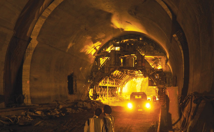
The tunnel has been constructed by using New Austrian Tunnelling Method (NATM) of sequential excavation and support system, the most advanced tunnelling technique available in the world.
The Chenani – Nashri Tunnel is 9 kms long single tube bidirectional tunnel with parallel 9 kms long Escape Tunnel and 29 cross passages. The tunnel is being constructed in the lower Himalayan ranges under the most challenging and difficult geology of young Himalayan mountains. The width of carriageway (clearance dimensions) for each tunnel typical section and some salient features are summarised below:
• Main tunnel: The paved carriageway is 9.35 metre wide and 1.2 metre footpath on each side. The vertical clearance is minimum 5 metre.
• Escape tunnel: The paved carriageway is 5 metre wide and the minimum vertical clearance is 2.5 metre.
• Cross Passage: The paved carriageway is 7.50 metre wide and the minimum vertical clearance shall be 4.5 metre. Cross passages are provided at every 300 metre.
• Fire fighting niches has been provided at every 150 metre on each side.
• Emergency call niches have been provided at every 150 metre on each side.
• Lay-byes have also been provided at every 1.2 km on each side.
• Tunnel service buildings (located near the portals).
• E&M lightening and ventilation of tunnels, SCADA, a fire control system and emergency call communications.
• Tunnel ventilation system at Chenani-Nashri is a fully transversal system. The fresh air is supplied and polluted air is extracted from inside Tunnel by the axial fans installed in Ventilation buildings at portal locations.
• The Chenani-Nashri tunnel fire detection system have alarm messages integrated in tunnel control system. The fire and alarm detection system will be characterised by fiber optical linear heat detector cable for tunnel fire detection, heat and smoke detectors for technical building fire detection, manual alarm button located inside SOS boxes. In case of fire near tunnel portals the smoke will be extracted by means of jet fans which are located at upper area of the tunnel tube by tunnel walls near tunnel entrance.
• Tunnel drainage: The sub surface drainage is installed in Main Tunnel (250 mm dia), Cross Passage and Escape Tunnel (150 mm dia). The subsurface drainage consists of rock mass drainage pipes collecting water from behind the concrete lining in Main Tunnel, Escape tunnel and Cross Passage and pass on to the longitudinal main drainage of 400 mm dia through transverse connections. There is another drain of 300 mm dia pipe on the left side of tunnel for the collection of surface water, this drain consists of 3 types of manholes at every 60 metre interval for the purpose of surface water, oil and fuel and collection from escape tunnel and Cross Passage.
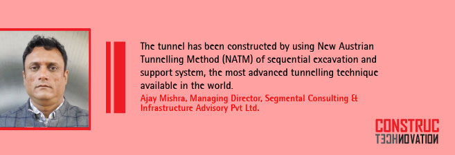
Informing about the tunnel construction Ajay Mishra, Managing Director, Segmental Consulting & Infrastructure Advisory Pvt Ltd said, “The tunnel has been constructed by using New Austrian Tunneling Method (NATM) of sequential excavation and support system, the most advanced tunnelling technique available in the world. The NATM integrates the principles of the behaviour of rock masses under the load and monitoring the performance of underground construction during construction. The main idea is to use the geological stresses of the surrounding rock mass to stabilise the tunnel itself. The method relies on the inherent strength of the surrounding rock mass being conserved as the main component of tunnel support. Primary support is directed to enable the rock to support itself.”
Loosening and excessive rock deformation must be minimised. This is achieved by applying a thin layer of shotcrete immediately after face advance. Every deformation of the excavation must be measured. NATM requires installation of sophisticated measurement instrumentation. It is embedded in lining, ground and boreholes.
The sequence of operations of tunnelling adopted in Chennai-Nashri is as follows:
• Surveying and profile marking.
• Drilling with a twin –drill jumbo as per the designed drilling pattern. Charging the drill holes as per pre- approved pattern and blasting by a licensed blaster, after due precautions. Excavation has been carried out in the Main tunnel in different phases such as Heading, Benching & invert but in Escape tunnel the excavation done as per full face excavation.
• Defuming followed by mucking. The removal of muck soil is carried out by wheel loaders, excavators and carted away by dump trucks at the dumping yard.
• Scaling and 3 D and face logging. The Geologists classify the type of the rock encountered and they will also suggest the need for the forepoling as well as the fore probing for the next round.
• Sealing of excavated face with 1st layer of shotcrete layer of 75 mm thick of M25 grade.
• Fixing of wire mesh 150 mm, 150 mm, and 6 mm. It consists of structural steel with minimum yield strength of 415 N/mm2.
• Installation of lattice girders having size depends upon the rock encountered at variable spacing also depends upon the class of rock (i.e 500 mm, 1000 mm).
• Spraying a 2nd layer of shotcrete of M-25 grade.
• Installation of convergence measuring instruments (i.e. Bi- reflex targets and pressure cells. Spacing of targets has been provided at every 10m or as directed by the Engineer- in- charge. Pressure cells and strain meter are also provided as per arrangement. The spacing could be decreased if there is need for better understanding of rock mass
• Installation of rock bolt SN type or IBO or Swellex bolts 4m/6m long at 1500mm in staggered pattern as per site condition and as directed by Engineer in charge. Where weak strata are encountered face bolting up to 9m length is also provided.
• After heading excavation is completed, analysis of deformation of heading zone, if there is no deformation in the tunnel, benching is commenced in the similar method of heading. The maximum lag of benching form heading shall be 100 m.
• Water proofing for all underground structures by means of continuous waterproofing membrane installed to the outside of the final concrete lining. The purpose of the membrane waterproofing is to prevent leakage of ground water in to the tunnels and to protect the final concrete lining against deleterious chemical influences.
• Inner concrete lining/final tunnel lining of M30 grade to provides a uniform interior face and improves the water tightness of the tunnel lining.
Segmental Consulting Infrastructure and Advisory Pvt ltd has been awarded this project as Independent Engineer for this project i.e. Construction of Chenani Nashri tunnel (9 Km ) long in the state of Jammu and Kashmir on DOBFT pattern and strengthening of Existing Highway from 89.000 km to 130.000 km. While sharing his views on company’s role in this project Mishra says, “Our Company is responsible for planning, site investigations result and covering the geo-technical interpretation, overall geotechnical study, preparation of report and review of documents. The preparation of quality assurance programs for the project being executed by adopting modern construction technology. Ensure adherence to specifications and standards for highway projects relevant to India and also to internationally accept best practices.”
He adds, “We look after setting up, organisation and layout of field testing laboratories and ensuring that the laboratories are staffed with qualified personnel and equipped with duly calibrated testing equipment. Monitor mobilisation of various testing equipment as per the specified testing requirements of the project. Maintain laboratories during the course of the project.”
The company’s responsibility also involves review of contract agreement, review of design and drawing and supervision of work as per Indian and international codal standards. Review of material receipt at site and testing as per codal provisions.
Segmental Consulting also played a role in:
• Identification of quarry and borrow areas.
• Conducting tests on soil, aggregates, bitumen, cement for confirming and assessing their adequacy and suitability.
• Ensuring quality control work by organising various field and laboratory tests including the following that is procter density, LL, PI, CBR, aggregate impact value, flakiness and elongation etc.
• Designing Job-Mix formula for DBM and BC, mix-design for WMM and GSB and concrete mix designs, maintaining of frequency of tests and documentation of all the testing records.
• Mix-design for shot crete and lining concrete.
• Calibration of hot-mix plant, WMM and concrete batching plant and all other testing equipment to ensure that the specified requirements for such equipment are fully met.
• Investigation of pavement using DCP and Benkelman Beam Deflection for ascertaining the maintenance requirements.
• Conducting plate load test.
• Supervise setting up of rock crushers in accordance with the project requirements.
• Preparation of various material testing reports.
Cookie Consent
We use cookies to personalize your experience. By continuing to visit this website you agree to our Terms & Conditions, Privacy Policy and Cookie Policy.
